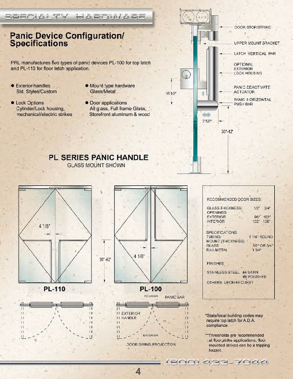
Panic Device Specifications: All Glass, Full Framed & Aluminum Panic Doors
Below we’ve provided our panic device specifications so your ordering and installations will go smoothly. Whether your emergency egress calls for all glass, full framed or aluminum doors, this page should be helpful to you. You’ll find technical information and installation tips for our panic devices, exterior panic handles, manual and electric strikes, and more.
At PRL, supplying premium quality products with exceptional customer service is our top priority. So, if you don’t see what you need here, just contact one of our knowledgeable representatives. We’ll be happy to answer your questions. Delivering our own glass door panic systems, full framed and aluminum fire exits to the glazing industry since 1989, it’s no wonder we’re the place specifiers and architects turn to first.
Panic Device Specifications, Finishes & Recommendations
We’ve designed our panic devices to prevent locked emergency egress doors from being forced open from the exterior. We’ve also improved the cylinder design so keys won’t jam in the lock housing. This has been done by using stronger components than other manufacturers.
Panic Device Specifications:
- Tubing Diameter: 1 ¼”
- Available Profiles: Round & square
- Accepts Glass Thicknesses: ½” & ¾”
- Rail/Metal: 1 ¾”
Panic Device Finishes:
- Brushed & polished stainless steel
- Satin & polished brass
- Oil rubbed bronze
- Powder coats & Kynar paints
Recommended Glass Door Thicknesses & Sizes:
- Glass Thicknesses: 1/2″, 3/4″
- Exterior Door Sizes: 96” & 102”
- Interior Door Sizes: 102” & 108”
Panic Components & Installation Tips
F-Style Exterior Panic Handle:
PRL’s panic devices can be used on doors up to 120” tall using the F-style exterior panic handle and ¾” thick glass. To compensate for the height of panic devices on taller doors, we’ve implemented stronger design methods. Our panic devices can be used on all glass, full framed and aluminum doors up to 48” wide.
To ensure compliance with A.D.A. regulations, local city codes should be verified prior to specifying the F-style exterior panic handle. Some state’s A.D.A. codes prohibit exterior handles to extend beyond 10″ from the bottom of the door.
Panic Pull Handle Tubes:
1-1/4″ diameter with .083 wall thickness. All moving mechanisms are made of 303 stainless steel and 360 brass where no stress is implemented.
Manual Strikes:
Made of 303 stainless steel in satin and polished finishes. Mounting bars for electric strikes are made from 6063-T5 aluminum clad in stainless steel or brass.
Electric Strikes:
Folger Adams 310-1 electric strikes are supplied with panic devices as a standard when electric strikes are specified. Some customers choose to supply their own. It is imperative that the function of the lock is specified in accordance with the building specification.
Non-Fail Safe Strikes:
The most common strike is a non-fail safe strike which remains locked when the power fails (24VAC is standard). On the fail-safe model, when power is applied, the solenoid pushes the locking cam into the locking position and the door cannot be opened. If the power fails the strike will unlock. This allows access to the building from the exterior in the event of a power failure.
All fail-safe strikes operated by DC solenoids are silent operation. For this reason, it’s important the type of strike is determined during the specification phase.
Headers:
A 1-3/4″ x 4″ or 4-1/2″ header can be used with panic devices when an electric strike is used, however a portion of the strike will be exposed. To eliminate this condition, a 6″ wide header can be utilized concealing the entire strike. If a smaller header is used, the exposed part of the strike is clad to match the header finish.
Door Jamb Conditions:
When installing an exterior horizontal handle, door jamb conditions may become an issue.
Exterior Handles Hitting Door Jambs:
When the door opens, the exterior handle may hit the door jamb if it’s too wide. To circumvent this issue, reduce the width of the horizontal bar by adjusting it closer toward the leading edge of the door.
Perpendicular Installation:
If the jamb is a wall that is perpendicular to the door, adjust the pivot point to 3 1/2″ to allow the horizontal bar to clear the wall.
Code Violation Note:
This adjustment will reduce the opening of the door, making it a code violation. To prevent code violations, door openings must be wide enough to allow for a 32″ clear opening when the door is fully opened. It is imperative this condition is addressed during the design phase.
It is advisable to use a no-hold open closer. This will allow the door to return to a closed position, thus locking the door.

